Research
Saturated and Efficient Blue Phosphorescent Organic Light Emitting Devices with Lambertian Angular Emission
C.L. Mulder, K. Celebi, and M.A. Baldo
Sponsorship: NSF
The realization of stable blue phosphorescent organic light-emitting devices (OLEDs) has proved challenging. An important limitation is the broad photoluminescent (PL) spectrum characteristic of organic dyes. For example, greenish-blue or “sky-blue” phosphors have strong emission in the blue [1]. But optical transitions to higher vibrational modes of the electronic ground state extend their emission spectrum deep into the green. Because the eye responds strongly at green wavelengths, this broad emission spectrum yields an unsaturated color that is ill suited for most display applications.
Synthesizing new phosphors with larger triplet energies may not help. Further increases in the exciton energy render a blue phosphor incompatible with most host materials, limit the molecular design possibilities, and inevitably exacerbate degradation process. Rather, it may be preferable to modify the OLED structure and filter out the unwanted long wavelength phosphorescence. This approach exploits the compatibility of sky blue phosphors with a broader range of host materials and operational lifetimes exceeding 15 000 h at an initial brightness of 200 cd/m2.[2]
In this work [3] a strong microcavity is employed to optimize the color of a phosphorescent organic light emitting device (OLED) based on the sky blue phosphor FIrpic. The usual disadvantages of a strong microcavity, namely the introduction of an angular dependence to the OLED’s color and a non-Lambertian angular emission profile [4], are overcome by scattering the emitted radiation. As scattering sources, frosted glass, opal glass, and holographic diffusers are studied.
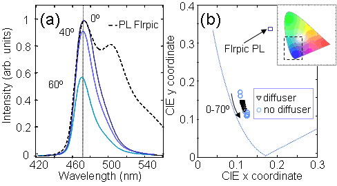
With a holographic diffuser as the scattering medium, the microcavity OLED achieves an external quantum efficiency of (5.5±0.6)%, as compared to (3.8±0.4)% for a conventional structure. The color coordinates of the microcavity OLED with holographic diffuser are (x,y) = (0.116±0.004, 0.136±0.010), with minimal angular color shift and a nearly ideal Lambertian angular emission profile.
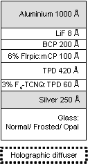
Fig. 1 In the strong microcavity the anode is a thin,semitransparent layer of Ag. The cathode is Al/LiF. Devices were grown directly on the smooth back surface of frosted glass and opal glass diffusers. The holographic diffuser was employed external to devices grown on regular glass.
Fig. 2 (a) Electroluminescent spectra of the strong microcavity FIrpic OLED as a function of angle from the surface normal with the holographic diffuser. A color shift with increasing angle is barely perceptible. For comparison we plot the intrinsic photoluminescent spectrum of FIrpic. :(b)The color coordinates of the strong microcavity devices with and without holographic diffusers. Inset: the full CIE diagram identifying the expanded blue region.
Relevant Publications
- C. Adachi, R.C. Kwong, P. Djurovich, V. Adamovich, M.A. Baldo, M.E. Thompson, and S.R. Forrest, Appl. Phys. Lett. 79 (13), 2082 (2001).
- M.S. Weaver, R.C. Kwong, V.A. Adamovich, M. Hack, and J.J. Brown, J. of Info. Display 14 (5), 449 (2006).
- C.L. Mulder, K. Celebi, K. M. Milaninia and M.A. Baldo, ‘Saturated and Efficient Blue Phosphorescent Organic Light Emitting Devices with Lambertian Angular Emission’, Applied Physics Letters, 90, 211109 (2007).
- R.H. Jordan, L.J. Rothberg, A. Dodabalapur, and R.E. Slusher, Appl. Phys. Lett. 69 (14), 1997 (1996).


